

Microfluidic chips find applications in bio-sensors and PCR tests among many others. I personally find them extremely interesting because they lie at the intersection of life sciences and electronic/mechanical engineering. To get started with microfluidics, the first step I needed to take was to find a way to prototype these chips at low volumes.
First, just in case...
What is a microfluidic chip?
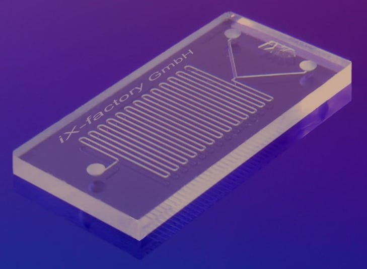
Think of a microfluidic chip as a PCB / circuit-board for fluids. It will route fluids from one location to another. Just like PCBs, microfluidic chips also have components built into them that perform functions beyond just transporting fluid from one location to another. One example of such a component would be a bubble generator that takes an incoming continuous fluid stream and converts it into discrete bubbles like in the video below (credit: Churchman, Adam H. (2018) doi:10.5518/153).
Microfluidic Chip Structure
Microfluidic chips can be manufactured in many different ways all with their own unique advantages. I've shown the structure of my setup below.

We have two soft layers sandwiched between two hard plastic layers.
The circuit pattern is etched onto the bottom soft layer and entry/exit ports for the liquid are cut out of the top plastic and soft layers. The whole fabrication process is performed on a laser cutter. There is also post-processing in the form of applying pressure and heat onto the setup so as to ensure that the fluid channels seal properly.
The primary purpose of the top soft layer is to help the circuit seal. Ideally I would also want another soft layer with no etching on it between the bottom soft and backing layers - unfortunately this ended up causing manufacturing issues.
Prototyping Issues
As usual, there were plenty of issues I encountered during prototyping, the ones below were interesting enough to mention. Feel free to skip to the end of the article to see the final result.
Soft Layer Material Selection
There were three considerations with selecting the right material for the soft layer.
The soft layer must be soft enough to seal but not so soft that it deforms during post processing or handling
It must be possible to safely etch away the soft layer using a laser cutter (specifically - the one already in the workshop)
It must be possible to somehow bond this material to the backing plastic
Inconsistent Channel Width

The soft layer is etched with a laser cutter. The laser cutter I am using slows down as it approaches a sharp turn so that it can make an accurate adjustment to it's direction when it's time to turn. This causes heat to build up over the region where the laser is travelling slowly and takes away more material compared to other areas. This issue was mostly harmless so I ignored it at first but eventually found a way to solve it while working on the next issue.

Cutting Through The Backing Layers
Another side effect of the slow down mentioned above is that if it slowed down enough, it would cut right through the backing layer and allow liquid to leak out the back. This issue was solved by reducing the power of the laser only when it slowed down. This also mostly resolved the previously mentioned issue with channel width consistency.
Blocked Channel

If the heat and pressure applied during post-processing are too high then we will end up with the soft layers melting into the etched channels and extruding out of every opening - rendering the circuit blocked and useless. The channels are about 0.25mm wide, so it doesn't take much to accidentally block them.
Layer Delamination Leakage
If the seal between the two soft layers isn't very good then liquid will very easily find it's way around the channels.
While I have made some effort to improve this seal through post processing, it's quite hard to create a perfect seal and even good seals seem to eventually break.
My current hypothesis on why this happens is: there are small imperfections in the seal between the two soft layers. As the fluid flows under pressure, these small imperfections force the two layers apart (like using a wedge to split wood). This causes the gap to become even bigger and makes it even easier to force the two layers apart until eventually liquid leaks out the side.

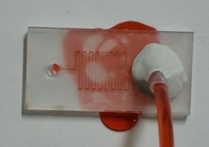
A quick and hacky way to solve this for now is to just seal off the sides of the chip and that way the liquid (mostly) won't go down that path. This solution isn't very good though as it isn't reliable and still sometimes leads to minor leakage out of the channels (but not out of the sides). I don't like this as it's more of a band-aid than a solution to the core issue, so in the future I will likely try and find a better way to solve this.

Prototype and Conclusion
Overall I'm quite excited about how this turned out - especially the ~0.25mm channel width that was achieved was significantly better than expected. This is also a very quick and efficient way of fabricating these chips - it takes just about 15 minutes to make a one-off chip. The delamination issue issue isn't completely resolved, so that's probably going to be my main focus for the next attempt.
After that I would be very interested in trying to etch a valve or droplet generator right into the soft layers without adding any external devices.
